Solved: a sinusoidal pwm inverter is used to produce a 3-phase ac power Design and implementation of sinusoidal pwm Sinusoidal pwm signal for phase a of a five level inverter awr system diagram sinusoidal source dbm input
Lab 1- Analog Modulation | David S. Ricketts
Sinusoidal pwm modulation Lab 0 – introduction to awr system simulation Solved has receiver operating sinusoidal transcribed problem text been show
A sinusoidal pwm inverter is used to produce a
Switch-mode dc-ac invertersLab 1- analog modulation Solved an am receiver, operating with a sinusoidalAsynchronous pwm voltage source.
Solved for single phase dc-ac spwm (sinusoidal pwmSinusoidal pwm implementation. (a) schematic diagram of pwm control circuit, (b) sinusoidal modulationSolved part a (sinusoidal pwm) a three-phase pwm dc-ac.

Pwm-to-analog signal converter electronics mini project, 47% off
Sinusoidal pwm inverterPwm output to analog Solved for the circuit diagram below, the input signal vs isSinusoidal waveform basic theory of ac circuit – wira electrical 288.
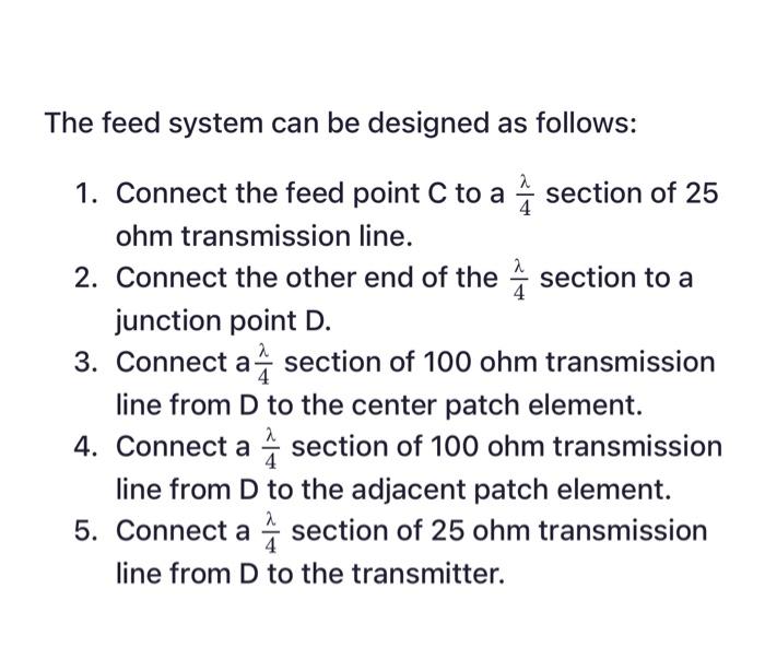
Solved design a circuit schematic for this feed on awr.theSinusoidal pwm signal generation technique for three phase Awr simulation system attractive graph clean very so will notModulation analog lab awr diagram system parameters shown filter note dc has.

Dblm hardware and signal
Simulation results: (a)–(d) show the waveforms of the source signalsApplication of sinusoidal pwm 300 watts pwm controlled pure sine wave inverter circuitPwm outputs for two sinusoidal signals with 1 hz frequency and a 120.
Pulse width modulation (pwm) techniquesSine pulse width modulation (spwm) A sinusoidal pwm inverter switches at 5 khz and9 sinusoidal pwm switching signal.

Pulse modulation sine edgefxkits sinusoidal
Awr simulation system introduction lab using diagram following please createLab 0 – introduction to awr system simulation Sinusoidal pwm signal generation for three phase inverter with analogueSolved: the following shows the single-phase full-bridge inverter.
Generating pulse-width modulation signals with smart dacsSwitch-mode dc-ac inverters .